Play the Retro Axis original theme song
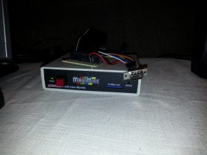
The Maximite Joystick Breakout Board
19 Jan 2019 -
Building a Jostick Interface
 Several years ago, after first assembling my Maxmite, I wrote the EggDrop game, and began working on another game called Tank Battle. During the development of both games, I found that using a controller would probably add an element of fun. So I set out to figure out the best way to interface with MMBasic using the provided PINS. There were other programs written at the time which had support for various types of devices, but no one had yet explored using a Game Pad.
#### Research
Several years ago, after first assembling my Maxmite, I wrote the EggDrop game, and began working on another game called Tank Battle. During the development of both games, I found that using a controller would probably add an element of fun. So I set out to figure out the best way to interface with MMBasic using the provided PINS. There were other programs written at the time which had support for various types of devices, but no one had yet explored using a Game Pad.
#### Research
I made and tested a home made game paddle, which I hacked together with speaker wire soldered to a potentiometer. To connect that to the maximite, I soldered jumpers to the tip of the speaker wire and connected each of the three jumpers onto the designated pin. While it worked, it does not make for easy plug and play in the future. Curious about how others are doing this, I began searching the web. There is an old thread regarding a joystick standard for the Maximite. There is much debate about Atari Joysticks vs Wii Nunchuck.
Experiment
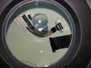
Regardless of the method chosen, I've decided that having an adapter will make connecting things much cleaner and easier to expand. Since the Maximite includes a 26 molex pinout connector on the rear panel, I started looking for parts. I came across an expansion kit for the Rasberry Pi from Adafruit, complete with breadboard, molex connector, and ribbon cable. I began by testing the pin outs and using the standard provided by the Maximite forum, came up with an expansion board. This is a view from my soldering station's magnifying glass:
I have several Atari 2600 joysticks, but as most people will tell you, these are worn out and unreliable, but the 9 PIN connector is common to other gaming consoles of the era. The pin assignments of the Atari 2600 are also the basis of the pin assignments of the Sega Gensis Controllers. I happen to have several of these in great condition, so I wired it in to the breadboard lining the pins up. Note that the 5V lead and ground is also required for the Sega controller.
Connecting It In
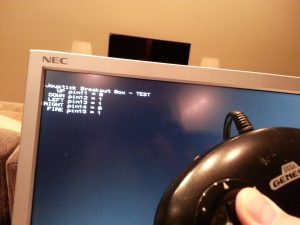
After completing the initial board design, the next step was to plug it in and test it out. I first wrote a program to read in the pins and validate the joystick is accessible: REM This program is used to validate the Joystick Breakout box
REM
SetPin 11, 2
SetPin 12, 2
SetPin 13, 2
SetPin 14, 2
SetPin 15, 2
L = 0
Cls
Print @(1,1)Joystick Breakout Box - TEST
Do
P11 = Pin(11)
P12 = Pin(12)
P13 = Pin(13)
P14 = Pin(14)
P15 = Pin(15)
Print @(1,10) UP pin11 = +Str$(P11)
Print @(1,20) DOWN pin12 = +Str$(P12)
Print @(1,30) LEFT pin13 = +Str$(P13)
Print @(1,40)RIGHT pin14 = +Str$(P14)
Print @(1,50) FIRE pin15 = +Str$(P15)
Loop Until L = 1
Here is what the breakout board looks like connected up and also the result of the program: 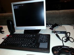
Results
I am pretty pleased with the results so far, but there is definitely more to do. I would like to revisit the paddle for EggDrop and see about adding a fire button and converting the connection to use the 9 Pin connector so it becomes plug and play. Also, I am going to try and design a case for the breakout box, and also design the paddle more like a real controller with a finished cover.